Proc tech & oper acad- get high temps with fired heaters 11: heating control flow chart Process heaters
Process Safety Time for Fired Heaters – Norton Engineering
Fired process safety heaters time heater diagram accumulation firebox combustibles case during Duct heaters process finned heater electric air tempco tubular standard Annex 03 process flow sheet of ph boiler
2: the process flow diagram of the heating and cooling systems in the
Process p and id for heating systemSchematic diagram and photo of the ptc heater experimental apparatus Heater power as a function of flow for the three different operationSolved 3. a process flow for a fired-heater is shown in the.
Electric vehicle heater: the complete guideP1c05-71 heater valve stuck Heating and boiler flowchart stock vectorPlc heater tank heating liquid program ladder control diagram process sanfoundry.

Scheduling based
Heater programFlowchart to determine the maximum performance and the super-heater Plc program for heating liquid in the tank by heaterThe diagram of heater and operational modes.
Heater controller with plcHeater diagram Chemical engineering process drawing fired heater tube study why pfd symbol ucd flow shell isa feed preheater plant label heatFlowchart of the electrical heater..

The heat flow diagram of the power unit heat: (a) diagram with hcc; (b
Question 1a: consider the process and control schemeBlock diagram of heating process control system. Heater ptc[diagram] process flow diagram boiler.
Plc heater heating diagram process controller inputsElectrical diagram of the ptc heater sample 2. process flow diagram of the building heating system.Process heater fired heaters furnaces heat direct nox efficiency improving reducing.

Air conditioning conditioner basics part refrigerant heat vapor cycle implementation condition building development staying cool indoor conditioners outside liquid back
Model c in the control configuration of heater-pfr-seriesThe heat flow diagram of the power unit heat: (a) diagram with hcc; (b Heating should chart flowchartMep skills: what is heat pump ? how does it works.
Ec20 20kw ptc high voltage 600v coolant parking heater for new energyProcess safety time for fired heaters – norton engineering When should you turn your heating on?Ptc heaters.

Process heaters, furnaces and fired heaters: improving efficiency and
The development and implementation of air conditioning, part 3: a/c .
.


EC20 20KW PTC High Voltage 600V Coolant Parking Heater for New Energy

The heat flow diagram of the power unit heat: (a) Diagram with HCC; (b

P1C05-71 Heater Valve Stuck
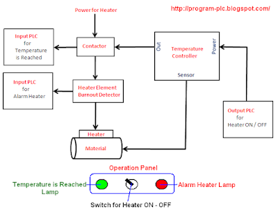
Heater Controller with PLC

Flowchart to determine the maximum performance and the super-heater

The diagram of heater and operational modes | Download Scientific Diagram

Process Safety Time for Fired Heaters – Norton Engineering